Final Mechanical Design
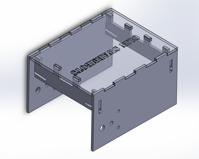
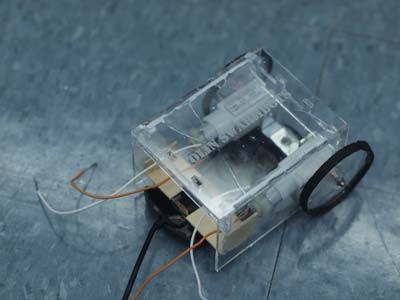
So just as a recap, we moved away from our initial track design because of the difficulty in correctly tensioning the track, and have designed our robot to drive via wheels attached to the motor itself. The design was fairly simple and straightforward (very similar in some ways to building a mousebot). We lasercut acrylic that attached to form a box-like shape.
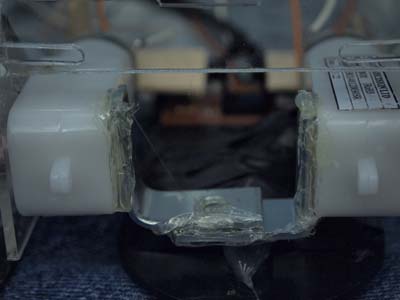
We’ve gone through 3 design iterations in acrylic: the first was building a “C” out of acrylic pieces that fit together similarly to woodjoints. However it didn’t have much support at the joints and we glued some thin-walled aluminum tubing to the corners. The second iteration involved two crossbraces that were designed to push into the frame and then slide up to lock. However due to tolerances the pieces usually slid down and didn’t have enough frictional force to hold. The third iteration was modeled after the Adafruit Raspberry Pi case that snaps together without glue. Since there wasn’t a hook on the top surface, the design still required glue, however the spring action in the crossbraces made it much easier to assemble than the 2nd iteration.
Our wheels are secured to the shaft using #2.5 x 12mm screws, washers, and some of the 0.625” and 0.500” diameter spacers we made. We found that if we tightened the wheels too tightly, there would be too much friction in between the wheel and the chassis.
Design improvements: Add a second “hook/nub” to the top surface of the spring loaded crossbrace, and make the edges that were meant to stick into the top panel a little longer so that they do stick into the top panel. Purchase fender washers to more evenly distribute the force to hold down the wheels. Due to the fact that we ended up using an arduino, it would probably be beneficial to make the robot slightly larger/manufacture a robot with a shelf in it and take out one of the cross braces. The shelf would add stability to the structure and would probably make the robot sound enough to remove the back crossbrace.